
 简体中文
简体中文 English
Website review
This review may include AI-generated content and is not individually verified. Domain, certificate and other facts come from the observed data on this page.
What is Raspberry Pi GPIO Pinout?
Raspberry Pi GPIO Pinout is an interactive reference for the Raspberry Pi's 40-pin GPIO header and the interfaces that run over it. It shows each physical pin number alongside its role: 3.3V and 5V power, ground, and GPIO lines labelled with alternate functions such as I2C, SPI, UART, PCM, PWM and GPCLK. The same site also catalogues pinouts for hundreds of add-on boards, HATs and pHATs, so you can check how a specific board maps onto the header before wiring anything.
What you can look up
- Pin roles and numbering: the difference between physical pin position and Broadcom GPIO number, which is the usual source of wiring mistakes.
- Interface groupings: which pins carry SPI0 (MOSI, MISO, SCLK, CE0, CE1), I2C1 (SDA, SCL), UART0 (TX, RX) and the EEPROM ID pins.
- Board compatibility: the HAT and pHAT explorer, useful when a board uses a non-obvious pin or conflicts with another add-on.
- Related boards: pinouts for the Raspberry Pi Pico range and RP2350 chip planners, plus a few experimental pinouts for non-Pi boards.
How people use it
A typical reader is holding a jumper wire over pin 11 and wants to know whether that is GPIO 17 and whether anything else already claims it. Another is choosing between two HATs and needs to confirm they do not both need the same SPI chip-select pin. A third is writing code and needs the correct Broadcom number rather than the physical position.
Practical notes
The header layout is fixed across current 40-pin Raspberry Pi models, so a pinout diagram remains valid across boards, but the alternate functions available on a given pin can differ by model and by software configuration. Treat the diagram as the wiring reference and the board's own documentation as the authority on what a HAT actually drives.
Before soldering or plugging in a HAT, pick your two or three intended pins, note their physical numbers and Broadcom numbers on paper, and confirm none of them collide with the interfaces your other hardware uses.
How do I find the pinout for a specific Raspberry Pi HAT or pHAT?
Open Raspberry Pi GPIO Pinout and use its board explorer, linked from the "Explore HATs & pHATs" section, to browse pinouts for add-on boards, HATs and pHATs. The site is primarily an interactive reference for the 40-pin GPIO header and the interfaces that share it — SPI, I2C, UART, PCM, PWM and others — with hundreds of add-on board pinouts alongside.
A practical way to use it
- Identify the exact board name and revision printed on the HAT or pHAT; near-identical boards can map pins differently.
- Search or browse the board explorer for that name and open its pinout page.
- Note which physical pins the board claims, then check them against the main 40-pin reference to see whether anything you already use — an I2C sensor, a UART console, a PWM fan — collides.
- If the board is not listed, fall back to the main pinout and the board's own documentation, and map its labelled signals (SDA, SCL, CE0, MOSI) to physical pin numbers yourself.
What the pinout actually tells you
The main reference labels each physical pin with its GPIO number and any alternate functions, for example GPIO 2 and GPIO 3 on physical pins 3 and 5 as I2C1 SDA and SCL, or GPIO 8 and GPIO 7 on physical pins 24 and 26 as SPI0 CE0 and CE1. Power and ground pins are marked separately: 3.3 V and 5 V supplies, and multiple ground pins spread along the header. Because a HAT sits on all 40 pins, its pinout is really a map of which of those functions it consumes and which it leaves free.
Quick comparison
| Situation | Best route |
|---|---|
| Common, well-known HAT or pHAT | Board explorer listing on the pinout site |
| Obscure or clone board | Board's own documentation, cross-checked against the 40-pin reference |
| Board not listed anywhere | Map its silkscreen labels to physical pins using the main pinout |
| Planning a stack of two boards | Compare both pinouts for shared I2C, SPI or power pins before buying |
Next step
Before wiring anything, write down the physical pin numbers your board needs and compare that list with the pins your other peripherals already occupy. If two boards both need SPI0 CE0, for instance, you will need a different chip-select pin or a different board — a conflict that is far cheaper to find on a pinout page than on a powered-up Pi.
What do the physical pin numbers and GPIO numbers mean on the Raspberry Pi GPIO header?
Physical pin numbers are positions on the 40-pin header; GPIO numbers are the Broadcom signal names the software uses. The header is numbered 1–40 in a zig-zag: odd pins run down one column, even pins down the other, with pin 1 at the end nearest the SD card when the GPIO is on the right and HDMI on the left. So "physical pin 11" is a location, while "GPIO 17" is the function you address in code. A single physical pin maps to exactly one GPIO number (or to power/ground), but that GPIO can also be routed to alternate interfaces such as I2C, SPI, UART, PCM, PWM or GPCLK.
Reading the two numbering schemes together
The interactive reference at Raspberry Pi GPIO Pinout lists each pin as a pair, for example:
- Physical pin 1 — 3v3 Power
- Physical pin 3 — GPIO 2 (I2C1 SDA)
- Physical pin 5 — GPIO 3 (I2C1 SCL)
- Physical pin 11 — GPIO 17
- Physical pin 19 — GPIO 10 (SPI0 MOSI)
- Physical pin 39 — Ground
The bracketed labels are the alternate functions available on that pin, not separate pins. Ground and power pins have no GPIO number because they are not programmable.
Why the distinction matters in practice
| Situation | What you use | Example |
|---|---|---|
| Wiring a sensor to a header | Physical pin number | "Connect SDA to pin 3" |
| Writing Python with gpiozero or RPi.GPIO | GPIO number | LED(17) for physical pin 11 |
| Using a HAT | Physical pin position | The board covers specific pins |
| Debugging a breadboard | Both | Trace pin 19 to GPIO 10 |
A common beginner mistake is passing the physical pin number into a GPIO library, so an LED on physical pin 11 stays dark because the code is toggling GPIO 11 (physical pin 23) instead of GPIO 17.
A concrete reader scenario
You are adding a DS18B20 temperature sensor. The wiring instruction says "data to physical pin 7." In code you enable the 1-Wire interface and read from GPIO 4, because physical pin 7 is GPIO 4. If you later move the wire to physical pin 11, the same code fails until you change the GPIO number to 17. Checking the pinout page before each rewire prevents that mismatch.
Next step
Before wiring anything, decide which scheme your tool expects: physical pins for the breadboard and HAT alignment, GPIO numbers for code. Then verify the pin's alternate functions, since a pin already used by I2C or SPI cannot also serve as a plain input without reconfiguring the interface. For Pico and RP2350 boards, the same site publishes separate pinouts, and general Raspberry Pi documentation at Raspberry Pi covers enabling interfaces through raspi-config.
Which GPIO pins support I2C, SPI, UART, or PWM interfaces?
On a 40-pin Raspberry Pi header, the alternate interfaces are tied to specific pins rather than being free for any GPIO. From the pinout reference at Raspberry Pi GPIO Pinout, the interface-labelled pins are:
| Interface | Physical pins | Signals |
|---|---|---|
| I2C1 | 3, 5 | GPIO 2 (SDA), GPIO 3 (SCL) |
| SPI0 | 19, 21, 23, 24, 26 | GPIO 10 (MOSI), GPIO 9 (MISO), GPIO 11 (SCLK), GPIO 8 (CE0), GPIO 7 (CE1) |
| UART0 | 8, 10 | GPIO 14 (TX), GPIO 15 (RX) |
| PWM | 32, 33 | GPIO 12 (PWM0), GPIO 13 (PWM1) |
| EEPROM (ID) | 27, 28 | GPIO 0 (SDA), GPIO 1 (SCL) |
Two practical wrinkles. First, I2C and SPI can coexist on the same header because they use different pins, but UART0 shares GPIO 14 and 15 with other functions, so enabling a serial console can conflict with a device wired there. Second, PWM is the most constrained: the reference marks only GPIO 12 and 13 as PWM0 and PWM1, so if you need several dimmable channels or servo pulses, plan around those two or accept software-timed PWM on other pins.
If you are wiring a sensor, a typical first step is to connect it to pins 3 and 5 for I2C, then confirm the address appears with i2cdetect -y 1 before writing any application code. For a display or radio module, use pins 19, 21, 23, 24 and 26 for SPI and check the chip-select pin your library expects. The same site also lists pinouts for add-on boards and HATs, which is worth checking before soldering, since a HAT may already claim the pins you intended to use.
How can I use the pinout diagram to wire a sensor or component to my Raspberry Pi?
Use the diagram as a physical-to-logical translator: start with your component's required interface (I2C, SPI, UART, or plain GPIO), find those signal names on the 40-pin map, then wire to the matching physical pin number. The page itself is an interactive reference to the GPIO pins and their interfaces, and it also documents hundreds of add-on board, HAT and pHAT pinouts.
A practical wiring routine
- Identify the interface, not just the wire count. A 4-wire sensor is often I2C (SDA, SCL, power, ground), while a display may be SPI. The legend on the diagram groups pins by function — GPIO, SPI, I2C, UART, PCM, plus 5V, 3.3V and Ground — so you can scan for the label rather than count holes.
- Translate label to physical pin number. The pinout lists entries like "GPIO 2 (I2C1 SDA) physical pin 3" and "GPIO 3 (I2C1 SCL) physical pin 5". Your sensor's SDA lead goes to physical pin 3, SCL to physical pin 5. Physical pin numbers are what you count on the header; GPIO numbers are what you use in code.
- Orient the board before you count. The legend instructs: orient your Pi with the GPIO on the right and the HDMI port(s) on the left. The page also offers a mirror view for the underside and a 180-degree rotation, which matters if you are soldering or using a ribbon cable.
- Match voltage deliberately. 3.3V and 5V power pins are marked separately. A 5V-only sensor output feeding a 3.3V GPIO input is a common way to damage a Pi, so check the component's logic level before connecting signal wires.
- Confirm in software. After wiring, detect the device on the bus (for example with an I2C scan) before writing application code. If nothing appears, re-check ground and the physical pin count first.
Worked example: an I2C temperature sensor
| Sensor lead | Diagram signal | Physical pin |
|---|---|---|
| VCC | 3v3 Power | 1 or 17 |
| SDA | GPIO 2 (I2C1 SDA) | 3 |
| SCL | GPIO 3 (I2C1 SCL) | 5 |
| GND | Ground | 9, 25, 39, and others |
Note that ground appears on many pins, so choose whichever is most convenient for your cable routing — the diagram labels each one.
When to use the add-on board section instead
If you are attaching a HAT or pHAT rather than loose components, the board explorer is the better starting point: it shows which pins that specific board claims, which tells you what remains free for your own sensor. This is the main trade-off between the two views — the 40-pin map is authoritative for the header itself, while board pinouts are authoritative for a stacked add-on.
For boards beyond the standard 40-pin header, the site also publishes pinouts for the Raspberry Pi Pico range and RP2350 chip planners, so the same label-to-pin method carries over to microcontroller projects.
Next step
Before powering up, sketch your connections as a table like the one above and keep it next to the Pi. Then verify each wire against the diagram's physical pin numbers rather than memory — mis-counting by one pin is the most common wiring error, and the numbered layout is designed to prevent exactly that. Official Raspberry Pi documentation at Raspberry Pi is a useful companion for confirming voltage and interface behaviour.
What are the differences between the Raspberry Pi 40-pin GPIO pinout and the Raspberry Pi Pico pinout?
The Raspberry Pi 40-pin GPIO header and the Raspberry Pi Pico's pinout differ in physical layout, voltage, and the mix of functions on each pin. The 40-pin header is a 2×20 connector on full-size Raspberry Pi boards; the Pico is a small microcontroller board with two rows of pins along its long edges, and its pin numbering does not match the 40-pin header's physical numbering.
Layout and numbering
- Raspberry Pi 40-pin header: pins are numbered 1–40 in a 2×20 arrangement. Odd pins run down one side, even pins down the other. Pin 1 is 3.3V power, pin 2 is 5V power, and grounds are interleaved (pins 6, 9, 14, 20, 25, 30, 34, 39). The same physical pin carries a BCM GPIO number and often an alternate function, such as GPIO 2/3 for I2C1, GPIO 14/15 for UART0, and GPIO 9/10/11 for SPI0.
- Raspberry Pi Pico: pins are numbered along each side, typically 1–20 on the left and 21–40 on the right when viewed from the top with the USB connector at the top. The numbering is a board-position convention, not a match to the 40-pin header. Many Pico pins map to RP2040 GPIO numbers, and several support multiple peripheral functions through the chip's flexible I/O mux.
Power and electrical differences
The 40-pin header exposes both 5V and 3.3V power rails, which suits boards that need 5V for USB or motor drivers. The Pico is a 3.3V logic device; its 5V pin is tied to USB VBUS and is not a general-purpose 5V supply in the same way. The Pico also has a 3V3_EN pin and a 3.3V output, and its GPIOs are not 5V-tolerant.
Peripheral functions
On the 40-pin header, functions are largely fixed by the board design, so a given physical pin has a known set of alternates. The Pico's RP2040 lets you route many peripherals to different pins, so the same function can appear on more than one pin. That flexibility is useful when a HAT-style board or wiring layout constrains which pins are free, but it also means you must check the pinout for the specific function you enable rather than assuming a fixed mapping.
Choosing between them
Use the 40-pin pinout as your reference when you are working with a full-size Raspberry Pi, especially with add-on boards, HATs, or pHATs that assume the standard header. Use the Pico pinout when you are working with the Pico, Pico W, Pico 2, or Pico 2 W, or when you are designing around the RP2040 or RP2350 chips. If you are moving a project between the two, do not carry pin numbers across; re-check power, ground, and signal pins for the target board.
A practical next step is to open the interactive reference at Raspberry Pi GPIO Pinout and compare the 40-pin diagram with the Pico pinout page before wiring anything. For example, if you are connecting an I2C sensor, confirm which pins carry SDA and SCL on your specific board, then verify the voltage level the sensor expects.
 Cloudflare
 Fastly
 Google Workspace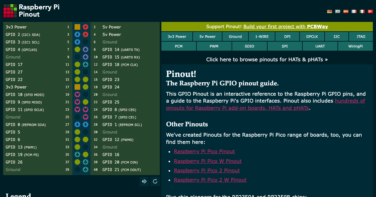
User reviews (0)